This page provides an overview of the Subpart W reporting requirements for the well venting for liquids unloading source category e-GGRT reporting requirements.type.
Please see Reporting Form Instructions instructions on downloading the blank reporting form and uploading the completed reporting form.
You may also refer to Optional Calculation Spreadsheet Instructions to download the Subpart W calculation spreadsheet.
The well venting for liquids unloading source category type is applicable to Onshore Petroleum and Natural Gas Productionto Onshore petroleum and natural gas production facilities (98.236(a)(2)).
Indicate if the facility has the source type via the radio buttons.
If the source type is present you must report the required
...
elements.
...
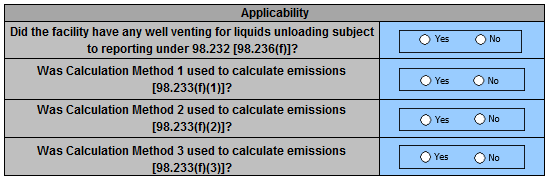
If the facility has the source type,
...
then indicate whether missing data procedures were used.
Reporting Requirements
Table F.1 Calculation Method 1 (counts, time, emissions)
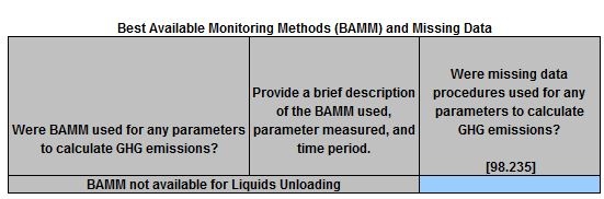
- For further information, see Best Available Monitoring Methods and Missing Data Reporting.
Worksheet Navigation
To navigate between tables use the navigational buttons provided at the top of the page and between tables or use the scroll bars.
...
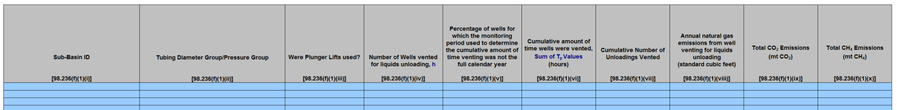
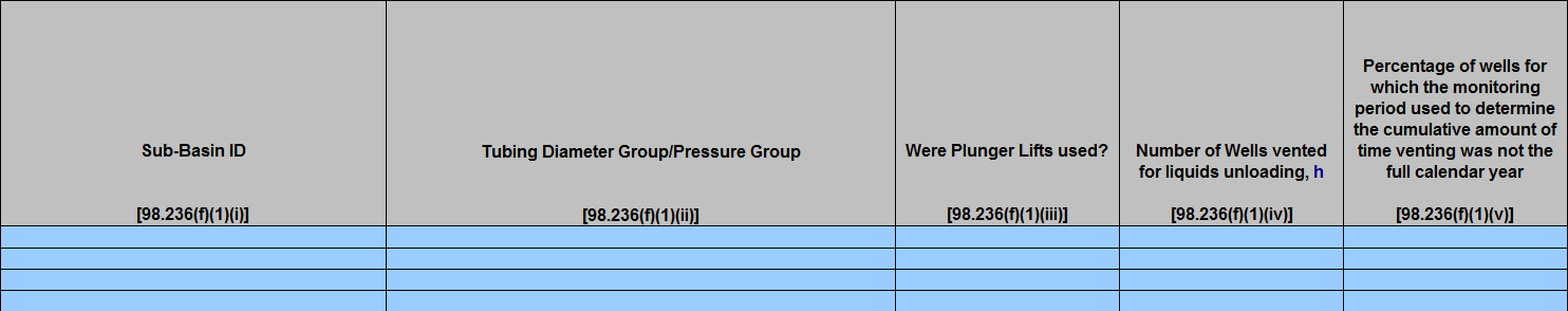
For Sub-basins using Calculation Method 1, the facility is required to report the following for each tubing diameter and pressure group combination within each Sub-basin category:complete Table F.1.
(Note: well-specific information for wells with liquids unloading must be reported in Table AA.1.iii)
- Sub-basin ID [98.236(f)(1)(i)] Sub-basin ID - the pick list for this data element is populated based on the Sub-Basin Selection Tabthe (aa)(1) Onshore Production tab of the Smart Form. Be sure a valid Sub-basin ID is used.
- Tubing diameter group/pressure group ([98.236(cf)(51)(iii)]
Were Plunger Lifts used? [98.236(f)(1)(iii)]
- <1 inch, <25 psig
- <1 inch, >25 psig and <60 psig
- <1 inch, >60 psig and <110 psig
- <1 inch, >110 psig and <200 psig
- <1 inch, >200 psig
- >1 inch and <2.375 inches, <25 psig
- >1 inch and <2.375 inches, >25 psig and <60 psig
- >1 inch and <2.375 inches, >60 psig and <110 psig
- >1 inch and <2.375 inches, >110 psig and <200 psig
- >1 inch and <2.375 inches, >200 psig
- >2.375 inches, <25 psig
- >2.375 inches, >25 psig and <60 psig
- >2.375 inches, >60 psig and <110 psig
- >2.375 inches, >110 psig and <200 psig >2.375 inches, >200 psig
- Number of wells vented for liquids unloading ([98.236(cf)(51)(iiv))Number of plunger lifts (]
Percentage of wells for which the monitoring period used to determine the cumulative amount of time venting was not the full calendar year [98.236(
cf)(
51)(
i)(B))v)]
Cumulative
numberamount of
unloadings vented within tubing diameter group/pressure groupAnnual total CO2 emissions (time wells were vented, Sum of Tp Values (hours) [98.236(
cf)(
51)(
i)(H))Annual total CH4emissions (vi)]
Cumulative number of unloadings vented [98.236(
cf)(
51)(
i)(H))For the single representative well in the sub-basin, the facility is required to report the following for each tubing diameter group and pressure group combination in the sub-basin category: Did well selected from the tubing diameter and pressure group have a plunger lift? (Yes or No) (vii)]
Annual natural gas emissions from well venting for liquids unloading (standard cubic feet) [98.236(
cf)(
51)(viii)]
- Annual total CO2 emissions [i)(B)) If Yes, the facility is required to report: Tubing pressure (98.236(cf)(51)(i)(G))Internal tubing diameter (ix)]
- Annual total CH4 emissions [98.236(cf)(51)(i)(E))
- If No, the facility is required to report:
- Casing Pressure (98.236(c)(5)(i)(F))
- Internal Casing Diameter (98.236(c)(5)(i)(E))
- Depth of the Well (98.236(c)(5)(i)(E))
For Sub-basins using Calculation Method 2, the facility is required to report:
- x)]
Table F.1 Calculation Method 1 (counts, time, emissions)
Enlarged View of Table F.1 Calculation Method 1 (counts, time, emissions)
Enlarged View of Table F.1 Calculation Method 1 (counts, time, emissions) (continued)
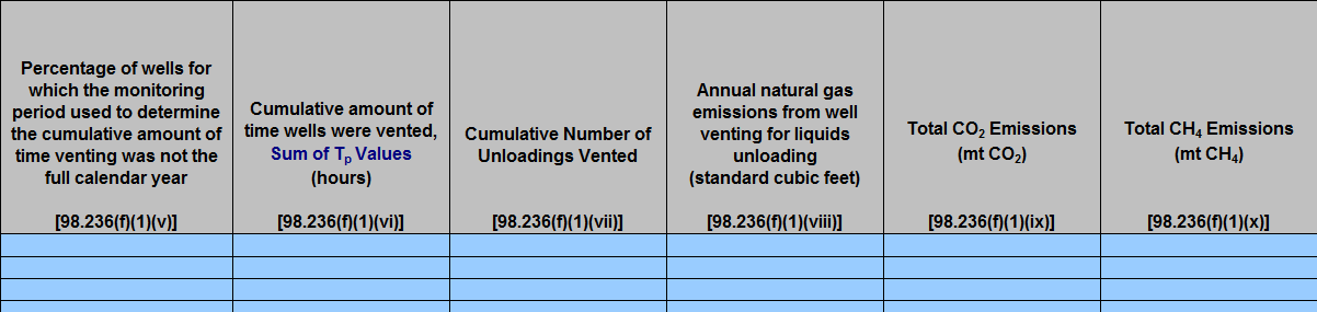
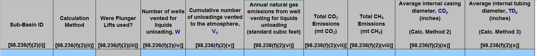
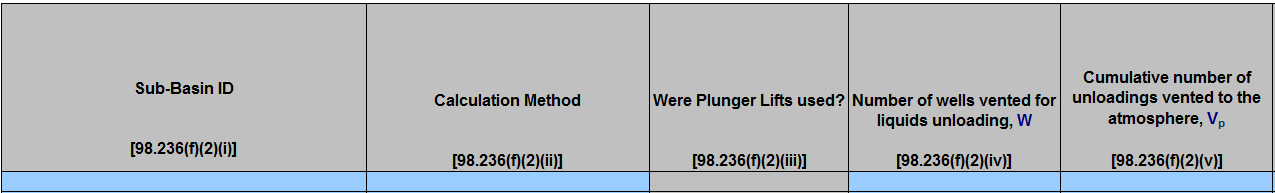
Table F.2 Calculation Method 2 & 3 (with or without plunger lifts)
For Sub-basins using Calculation Method 2 (without plunger lifts) and Calculation Method 3 (with plunger lifts), complete following table:
(Note: well-specific information for wells with liquids unloading must be reported in Table AA.1.iii.)
Sub-Basin ID [98.236(f)(2)(i)] - the
Sub-basin ID - thepick list for this data element is populated based on
the Sub-Basin Selection Tabthe (aa)(1) Onshore Production tab of the Smart Form. Be sure a valid Sub-basin ID is used.
Calculation Method [98.236(f)(2)(ii)]
Were Plunger Lifts used? [98.236(f)(2)(iii)]
Number of wells vented for liquids unloading
(without plunger lifts) ([98.236(f)(2)(iv)]
Cumulative number of unloadings vented to the atmosphere [98.236(f)(
c2)(
5)(ii)(A))- Average internal casing diameter (98.236(c)(5)(ii)(D))
- Total CO2 emissions (98.236(c)(5)(ii)(E))
- Total CH4 emissions (98.236(c)(5)(ii)(E))
For Sub-basins using Calculation Method 3, the facility is required to report:
v)]
Annual natural gas emissions from well venting for liquids unloading (standard cubic feet) [98.236(f)(2)(vi)]
Total CO2 Emissions (mt CO2) [98.236(f)(2)(vii)]
Total CH4 Emissions (mt CH4) [98.236(f)(2)(viii)]
Average internal casing diameter, (inches) [98.236(f)(2)(ix)] (for Calc. Method 2 only)
Average internal tubing diameter, (inches) [98.236(f)(2)(x)] (for Calc. Method 3 only)
Table F.2 Calculation Method 2 & 3 (with or without plunger lifts)
Enlarged View of Table F.2 Calculation Method 2 & 3 (with or without plunger lifts)
Enlarged View of Table F.2 Calculation Method 2 & 3 (with or without plunger lifts)(continued)
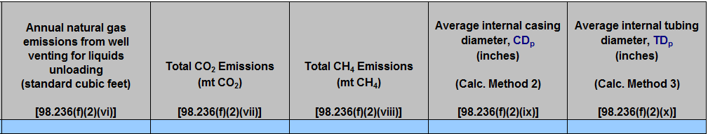
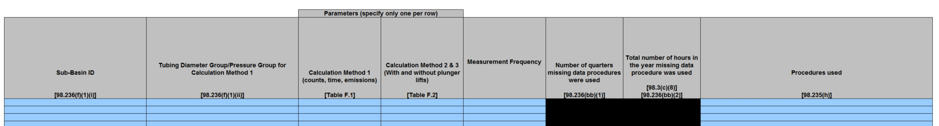
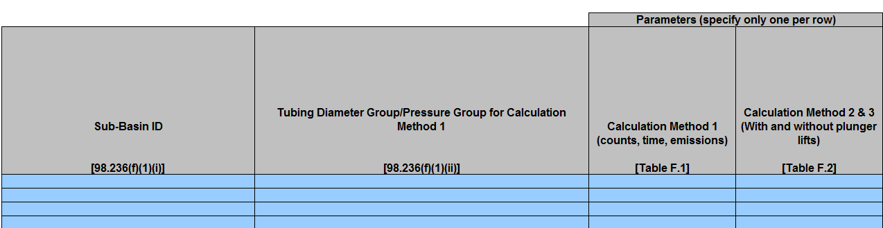
Table F.3 Missing data procedures used for Liquids Unloading emission calculations
If your facilities relied on missing data procedures to develop data elements used in calculating emissions for well venting for liquid unloading please report the following:
Sub-Basin ID [98.236(f)(1)(i)]
Sub-basin ID- the pick list for this data element is populated based on
the Sub-Basin Selection Tabthe (aa)(1) Onshore Production tab of the Smart Form. Be sure a valid Sub-basin ID is used.
- Number of wells vented for liquids unloading (with plunger lifts) (
Tubing Diameter Group/Pressure Group for Calculation Method 1 [98.236(
cf)(
51)(ii)
(A))Number of plunger lifts (]
- Parameters (specify only one per row)
Calculation Method 1 (counts, time, emissions) [Table F.1]
Calculation Method 2 & 3 (With and without plunger lifts) [Table F.2]
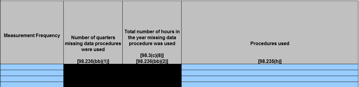
- Measurement Frequency
Number of quarters missing data procedures were used [98.236(
cbb)(
51)
(ii)(B))Average internal tubing diameter (98.236] (required only if the measurement frequency was quarterly)
Total number of hours in the year missing data procedure was used [98.3(c)(
5)(ii)(D))Total CO2 emissions (8)], [98.236(
cbb)(
52)
(ii)(E))- Total CH4 emissions (98.236(c)(5)(ii)(E))
...
] (required unless the measurement frequency was quarterly, annually, biannually, or N/A)
Procedures used for missing data [98.235(h)]
Table F.3 Missing data procedures used for Liquids Unloading emission calculations
Enlarged View of Table F.3 Missing data procedures used for Liquids Unloading emission calculations
Enlarged View of Table F.3 Missing data procedures used for Liquids Unloading emission calculations (continued)
Well–Specific Information - In addition to completing Tables F.1 – F.3, as appropriate, complete Table AA.1.iii with well-specific activity data for each well venting for liquids unloading (Tab (aa)(1) Onshore Production in the Smart Form) - see Onshore Production Facility Level Requirements.
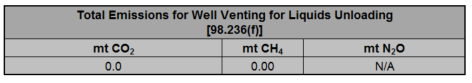
Total Emissions
The total emissions roll-up at the top of the sheet reflects the sum of each gas emission reported for the source type. These summations are calculated automatically by the Smart Form and tabulated on the Introduction tab.
...