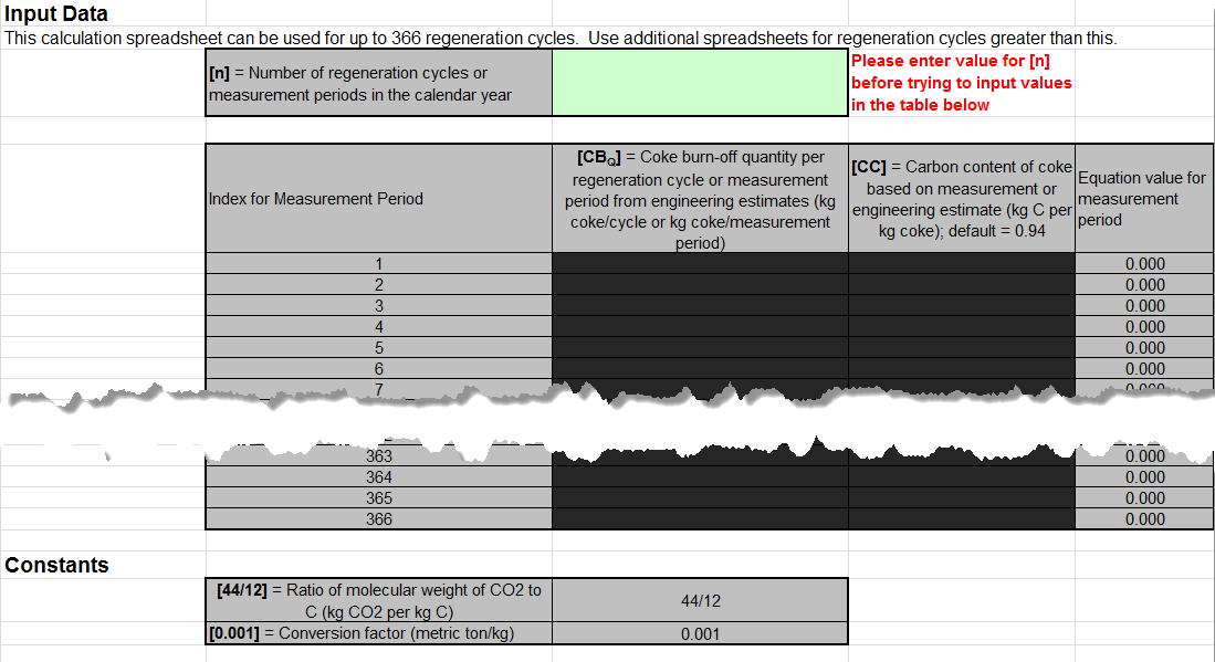
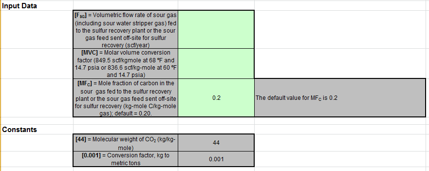
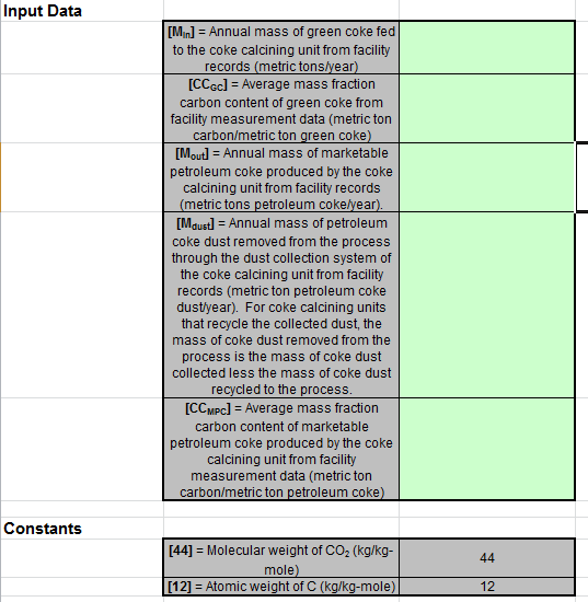
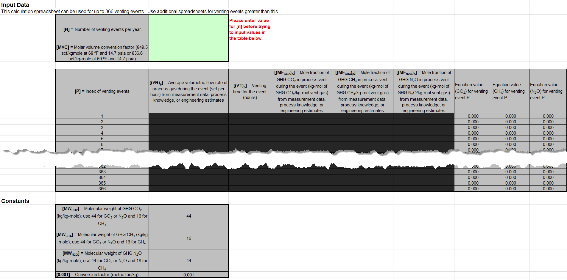
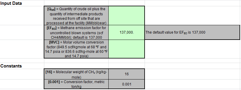
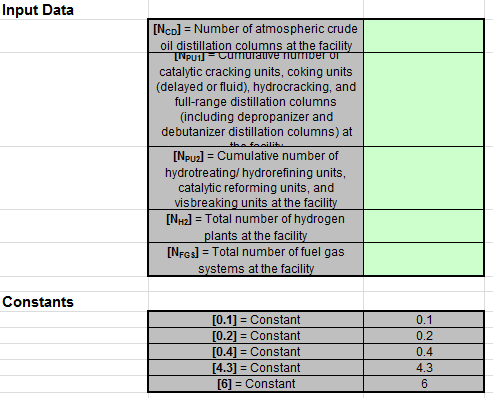
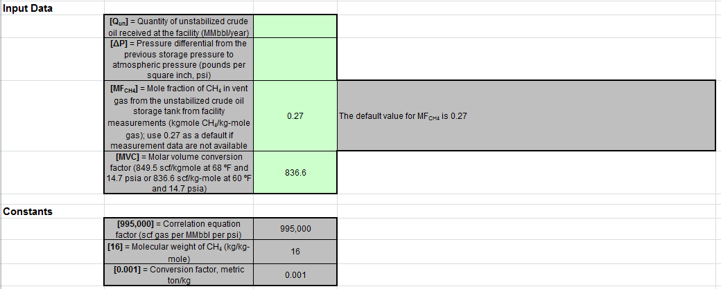
These optional spreadsheets are provided to assist reporters in calculating emissions and in keeping records of these calculations.
Reporters are required to keep records of these calculations under 40 CFR 98.3(g) and additional subpart-specific provisions, but are not required to use these spreadsheets or to submit any spreadsheets to EPA.
Overview
This help page provides guidance for working with the supplemental Subpart Y calculation spreadsheets. The guidance provides step-by-step instructions for the following tasks:
- Selecting the Appropriate Calculation Spreadsheet
- Downloading a Calculation Spreadsheet
- General Information on Using a Calculation Spreadsheet
- Using the Equation Y-1a Calculation Spreadsheet
- Using the Equation Y-1b Calculation Spreadsheet
- Using the Equation Y-2 Calculation Spreadsheet
- Using the Equation Y-3 Calculation Spreadsheet
- Using the Equation Y-4, Y-5 Calculation Spreadsheet
- Using the Equation Y-6, Y-7a, Y-7b Calculation Spreadsheet
- Using the Equation Y-8 Calculation Spreadsheet
- Using the Equation Y-9, Y-10 Calculation Spreadsheet
- Using the Equation Y-11 Calculation Spreadsheet
- Using the Equation Y-12 Calculation Spreadsheet
- Using the Equation Y-13 Calculation Spreadsheet
- Using the Equation Y-14, Y-15 Calculation Spreadsheet
- Using the Equation Y-16a, Y-16b, Y-17 Calculation Spreadsheet
- Using the Equation Y-18 Calculation Spreadsheet
- Using the Equation Y-19 Calculation Spreadsheet
- Using the Equation Y-20 Calculation Spreadsheet
- Using the Equation Y-21 Calculation Spreadsheet
- Using the Equation Y-22 Calculation Spreadsheet
- Using the Equation Y-23 Calculation Spreadsheet
Specific information on each of the calculation spreadsheets is provided below:
|
Calculation Spreadsheet |
Selection Criteria: |
Output(s) |
Instructions |
|---|---|---|---|
|
Flares |
CO2 |
||
|
Flares |
CO2 |
||
|
Flares |
CO2 |
||
|
Flares |
CO2 |
||
|
Flares |
CH4, N2O |
||
|
Catalytic Cracking Units or Fluid Coking Units |
CO2 |
||
|
Catalytic Cracking Units or Fluid Coking Units |
CO2 |
||
|
Catalytic Cracking Units, Fluid Coking Units, Coke Calcining Units, Catalytic Reforming Units |
CH4, N2O |
||
|
Catalytic Reforming Units |
CO2 |
||
|
On-Site Sulfur Recovery Plants, Sour Gas Sent Off-Site for Sulfur Recovery |
CO2 |
||
|
Coke Calcining Units |
CO2 |
||
|
Uncontrolled Asphalt Blowing Operations, Asphalt Blowing Operations Controlled by vapor Scrubbing |
CO2, CH4 |
||
|
Asphalt Blowing Operations Controlled by Thermal Oxidizer or Flare |
CO2, CH4 |
||
|
Delayed Coking Units |
CH4 |
||
|
Process Vents Not Covered in Paragraphs (a) through (i) of Section 98.253 |
CO2, CH4, or N2O |
||
|
Blowdown Systems |
CH4 |
||
|
Equipment Leaks |
CH4 |
||
|
Storage Tanks Other Than Those Processing Unstabilized Crude Oil |
CH4 |
||
|
Storage Tanks That Process Unstabilized Crude Oil |
CH4 |
Selecting the Appropriate Calculation Spreadsheet
Subpart Y requires facilities to report annual carbon dioxide (CO2), methane (CH4), and/or nitrous oxide (N2O) emissions from various types of equipment, systems, and operations at petroleum refineries including the following:
- CO2, CH4 and N2O emissions from each flare
- CO2, CH4, and N2O coke burn-off emissions from each catalytic cracking unit, fluid coking unit, and catalytic reforming unit
- CO2 emissions from sour gas sent off site for sulfur recovery operations
- CO2 process emissions from each on-site sulfur recovery plant
- CO2, CH4, and N2O emissions from each coke calcining unit
- CO2 and CH4 emissions from asphalt blowing operations
- CH4 emissions from equipment leaks, storage tanks, loading operations, delayed coking units, and uncontrolled blowdown systems
- CO2, CH4, and N2O emissions from each process vent not specifically included in paragraphs (a) through (g) of §98.253
- CO2 emissions from non-merchant hydrogen production process units (not including hydrogen produced from catalytic reforming units)
For certain emission sources, Subpart Y requires the use of CO2 CEMS when one is in place that meets certain requirements. Specifically, Subpart Y requires the use of CO2 CEMS if one is in place for the following sources: catalytic cracking units; traditional fluid coking units; catalytic reforming units; sulfur recovery plants; and coke calcining units. Refer to the help page for CEMS if you use a CO2 CEMS for one of these units. The spreadsheets considered in this help page should only be used for these units when a qualified CO2 CEMS is not used.
To determine which calculation spreadsheet(s) to use for your facility or company, consider the emission source and the GHG(s) emitted. For each emission source, use the corresponding calculation spreadsheet(s) to calculate emissions. Where reporting of multiple GHGs is required for a single emissions source, you may need to use multiple calculation spreadsheets for that emissions source. The calculation spreadsheet(s) appropriate for each emission source are detailed below.
Flares
Subpart Y requires affected facilities to report CO2, CH4, and N2O from flares. Five calculation spreadsheets are available to calculate emissions from flares. To calculate CH4 and N2O emissions from flares, use the Equation Y-4, Y-5 Calculation Spreadsheet. To calculate CO2 emissions from flares, select the appropriate calculation spreadsheet based on the follow criteria:
- If you monitor gas composition, calculate the CO2 emissions from the flare using either the Equation Y-1a or Equation Y-1b Calculation Spreadsheet. You may elect to use either equation. Equation Y-1b is more data intensive, but is expected to be more accurate, particularly if there is a high level of CO2 in the gas stream being sent to the flare.
- If you monitor heat content but do not monitor gas composition, calculate the CO2 emissions from the flare using the Equation Y-2 Calculation Spreadsheet.
- If you do not measure the higher heating value or carbon content of the flare gas at least weekly, determine the quantity of gas discharged to the flare separately for periods of routine flare operation and for periods of start-up, shutdown, or malfunction, and calculate the CO2 emissions using the Equation Y-3 Calculation Spreadsheet.
Catalytic Cracking Units and Fluid Coking Units
Subpart Y requires affected facilities to report CO2, CH4, and N2O from each catalytic cracking unit, each traditional fluid coking unit, and each fluid coking unit of flexicoking design that does not account for GHG emissions resulting from the use of low value fuel gas using the methods described in subpart C (General Stationary Fuel Combustion Sources). Three calculation spreadsheets are available to calculate emissions from these units. To calculate CH4 and N2O emissions from catalytic cracking units and fluid coking units, use the Equation Y-9, Y-10 Calculation Spreadsheet. To calculate CO2 emissions from catalytic cracking units and fluid coking units (that do not use a CO2 CEMS), select the appropriate calculation spreadsheet based on the following criteria:
- For catalytic cracking units and fluid coking units with rated capacities greater than 10,000 barrels per stream day (bbls/sd), use the Equation Y-6, Y-7a, Y-7b Calculation Spreadsheet to calculate the CO2 emissions.
- For catalytic cracking units and fluid coking units with rated capacities of 10,000 barrels per stream day (bbls/sd) or less that continuously or no less frequently than daily monitor the O2, CO2, and (if necessary) CO concentrations in the exhaust stack prior to combustion of other fossil fuels, use the Equation Y-6, Y-7a, Y-7b Calculation Spreadsheet to calculate the CO2 emissions.
- For catalytic cracking units and fluid coking units with rated capacities of 10,000 barrels per stream day (bbls/sd) or less that do not monitor at least daily the O2, CO2, and (if necessary) CO concentrations in the exhaust stack prior to combustion of other fossil fuels, use the Equation Y-8 Calculation Spreadsheet to calculate the CO2 emissions.
Catalytic Reforming Units
Subpart Y requires affected facilities to report CO2, CH4, and N2O from each catalytic reforming unit. Three calculation spreadsheets are available to calculate emissions from these units. To calculate CH4 and N2O emissions from catalytic reforming units, use the Equation Y-9, Y-10 Calculation Spreadsheet. To calculate CO2 emissions from catalytic reforming units (that do not use a CO2 CEMS), select the appropriate calculation spreadsheet based on the following criteria:
- For catalytic reforming units that continuously or no less frequently than daily monitor the O2, CO2, and (if necessary) CO concentrations in the exhaust stack prior to combustion of other fossil fuels, use the Equation Y-6, Y-7a, Y-7b Calculation Spreadsheet to calculate the CO2 emissions.
- For reforming units that do not monitor at least daily the O2, CO2, and (if necessary) CO concentrations in the exhaust stack prior to combustion of other fossil fuels, use the Equation Y-11 Calculation Spreadsheet.
Sulfur Recovery
Subpart Y requires affected facilities to report CO2 emissions from sour gas sent off site for sulfur recovery and CO2 process emissions from each on-site sulfur recovery plant. For most of these sources, only one calculation spreadsheet is available to calculate emissions from these sources. To calculate CO2 emissions from sour gas sent off site for sulfur recovery or from each on-site sulfur recovery plant (that does not use a CO2 CEMS), use the Equation Y-12 Calculation Spreadsheet. Alternatively, for non-Claus sulfur recovery plants (that do not use a CO2 CEMS), you may elect to use the process vent method, for which you would calculate CO2 emissions using the Equation Y-19 Calculation Spreadsheet.
Coke Calcining Units
Subpart Y requires affected facilities to report CO2, CH4, and N2O from each coke calcining unit. Two calculation spreadsheets are available to calculate emissions from these units. To calculate CO2 emissions from coke calcining units (that do not use a CO2 CEMS), use the Equation Y-13 Calculation Spreadsheet. To calculate CH4 and N2O emissions from coke calcining units, use the Equation Y-9, Y-10 Calculation Spreadsheet.
Asphalt Blowing Operations
Subpart Y requires affected facilities to report CO2 and CH4 from asphalt blowing operations. Two calculation spreadsheets are available to calculate emissions from asphalt blowing operations. To calculate CO2 and CH4 emissions from uncontrolled asphalt blowing operations or asphalt blowing operations controlled by vapor scrubbing, use the Equation Y-14, Y-15 Calculation Spreadsheet. To calculate CO2 and CH4 emissions from asphalt blowing operations controlled by thermal oxidizer or flare, use the Equation Y-16a, Y-16b, Y-17 Calculation Spreadsheet.
Delayed Coking Units
Subpart Y requires affected facilities to report CH4 emissions from each delayed coking unit. One calculation spreadsheet is available to calculate emissions from these units. To calculate CH4 emissions from delayed coking units, use the Equation Y-18 Calculation Spreadsheet. Alternatively, you may elect to use the process vent method for the depressurization cycle. If you elect this alternative, calculate CH4 emissions during depressurization using the Equation Y-19 Calculation Spreadsheet and calculate the CH4 emissions during vessel opening using the Equation Y-18 Calculation Spreadsheet. You will then need to add these emissions together to calculate the total CH4 emissions from the delayed coking unit.
Process Vents
Subpart Y requires affected facilities to report CO2, CH4, and N2O emissions from each process vent not covered in paragraphs (a) through (i) of §98.253 that can reasonably be expected to contain greater than 2 percent by volume CO2 or greater than 0.5 percent by volume of CH4 or greater than 0.01 percent by volume (100 parts per million) of N2O. This "process vent method" can also be used as an alternative methodology for certain other emission sources. One calculation spreadsheet is available to calculate emissions from these vents. To calculate GHG emissions from process vents, use the Equation Y-19 Calculation Spreadsheet.
Blowdown Systems
Subpart Y requires affected facilities to report CH4 emissions from blowdown systems. One calculation spreadsheet is available to calculate emissions from blowdown systems. To calculate CH4 emissions from blowdown systems, use the Equation Y-20 Calculation Spreadsheet. Alternatively, the Equation Y-19 Calculation Spreadsheet may be used to calculate CH4 emissions from uncontrolled blowdown systems.
Equipment Leaks
Subpart Y requires affected facilities to report CH4 emissions from equipment leaks. One calculation spreadsheet is available to calculate emissions from equipment leaks. To calculate CH4 emissions from equipment leaks, use the Equation Y-21 Calculation Spreadsheet. Alternatively, CH4 emissions from equipment leaks may be calculated using process-specific methane composition data (from measurement data or process knowledge) and any of the emission estimation procedures provided in the Protocol for Equipment Leak Emissions Estimates (EPA-453/R-95-017, NTIS PB96-175401). There are no calculation spreadsheets available for this alternative.
Storage Tanks
Subpart Y requires affected facilities to report CH4 from storage tanks. Two calculation spreadsheets are available to calculate emissions from storage tanks. To calculate CH4 emissions from storage tanks other than those processing unstabilized crude oil, use the Equation Y-22 Calculation Spreadsheet. Alternatively, CH4 emissions from storage tanks other than those processing unstabilized crude oil may be calculated using tank-specific methane composition data (from measurement data or process knowledge) and the emission estimation methods provided in AP-42, Section 7.1; there are no calculation spreadsheets available for this alternative. To calculate CH4 emissions from Storage tanks that process unstabilized crude oil, use the Equation Y-23 Calculation Spreadsheet.
Downloading a Calculation Spreadsheet
The table below summarizes the applicability of Subpart Y calculation spreadsheets relative to the various emission sources for petroleum refineries. Addition details are provided for each type of emissions source below the table. Calculation spreadsheets for Subpart Y may be downloaded by clicking one of the links in the first column of the table below. Users may also jump to instructions for each calculation spreadsheet by clicking one of the links in the fourth column.
|
Calculation Spreadsheet |
Selection Criteria: |
Output(s) |
Instructions |
|---|---|---|---|
|
Flares |
CO2 |
||
|
Flares |
CO2 |
||
|
Flares |
CO2 |
||
|
Flares |
CO2 |
||
|
Flares |
CH4, N2O |
||
|
Catalytic Cracking Units or Fluid Coking Units |
CO2 |
||
|
Catalytic Cracking Units or Fluid Coking Units |
CO2 |
||
|
Catalytic Cracking Units, Fluid Coking Units, Coke Calcining Units, Catalytic Reforming Units |
CH4, N2O |
||
|
Catalytic Reforming Units |
CO2 |
||
|
On-Site Sulfur Recovery Plants, Sour Gas Sent Off-Site for Sulfur Recovery |
CO2 |
||
|
Coke Calcining Units |
CO2 |
||
|
Uncontrolled Asphalt Blowing Operations, Asphalt Blowing Operations Controlled by vapor Scrubbing |
CO2, CH4 |
||
|
Asphalt Blowing Operations Controlled by Thermal Oxidizer or Flare |
CO2, CH4 |
||
|
Delayed Coking Units |
CH4 |
||
|
Process Vents Not Covered in Paragraphs (a) through (i) of Section 98.253 |
CO2, CH4, or N2O |
||
|
Blowdown Systems |
CH4 |
||
|
Equipment Leaks |
CH4 |
||
|
Storage Tanks Other Than Those Processing Unstabilized Crude Oil |
CH4 |
||
|
Storage Tanks That Process Unstabilized Crude Oil |
CH4 |
Using a Calculation Spreadsheet to Make Calculations
The guidance provided in this section applies to each of the calculation spreadsheets for Subpart Y. Additional guidance is provided for each individual calculation spreadsheet in the sections below.
Color coding
The calculation spreadsheets contain green input cells, gray informational cells, and red-bordered results cells filled with yellow or white. Users should use green input cells to enter all data specific to their facility, unit, or process. Gray informational cells contain parameter names, column and row headings, equation constants and subtotals. Calculation results are displayed in red-bordered results cells filled with yellow or white. For red-bordered, yellow-filled results cells, the values in these cells should be entered in the appropriate and separate calculation spreadsheet (as directed below cell) where additional calculations will be made. For red-bordered, white filled results cells, the values in these cells should be entered in e-GGRT for the appropriate process units. All cells that are not green input cells are locked and cannot be modified.
|
Green input cell (data entry) |
|
Gray informational cells (locked) |
|
Red-bordered, yellow-filled results cells (enter in appropriate and separate calculation spreadsheet) |
|
Red-bordered, white filled results cells (enter in e-GGRT) |
Stop and Warning Messages
The calculation spreadsheets will display a stop message if the user enters a value that is invalid or a warning message if the user enters a value outside the EPA estimated range for a particular data element. For invalid data entries, the stop messages will not allow a user to proceed and the user must reenter valid data before moving forward. For data entries that are outside the EPA estimated range for a particular data element, the warning messages will allow a user to proceed if the user deems the entered value to be accurate.
Multiple Units
For emissions sources under Subpart Y that require emission data to be reported for each unit, use separate calculation spreadsheets for each unit. Do not aggregate data for multiple units when calculating emissions from these sources using these calculation spreadsheets.
Using the Equation Y-1a Calculation Spreadsheet
If you monitor gas composition, you may use the Equation Y-1a Calculation Spreadsheet to calculate annual CO2 emissions for each fuel type combusted in each flare using the average carbon content of the flare gas combusted. A separate spreadsheet should be used for each flare and fuel type combination. In nearly all cases, gas sent to a flare will be a mixture of different process gases, which are collectively considered to be fuel gas. As such, Equation Y-1a would be applied once for this fuel type. If you monitor separately the fuel gas sent to the flare and natural gas added to the flare for the purposes of preventing oxygen infiltration or ensuring adequate heating value of the gas flared, you should calculate the CO2 emissions separately for these fuels and sum the values for subsequent reporting. You do not need to separately calculate or report CO2 emissions from natural gas used as pilot gas for the flare. Equation Y-1a is provided below.
|
(Equation Y-1a) |
|
|---|
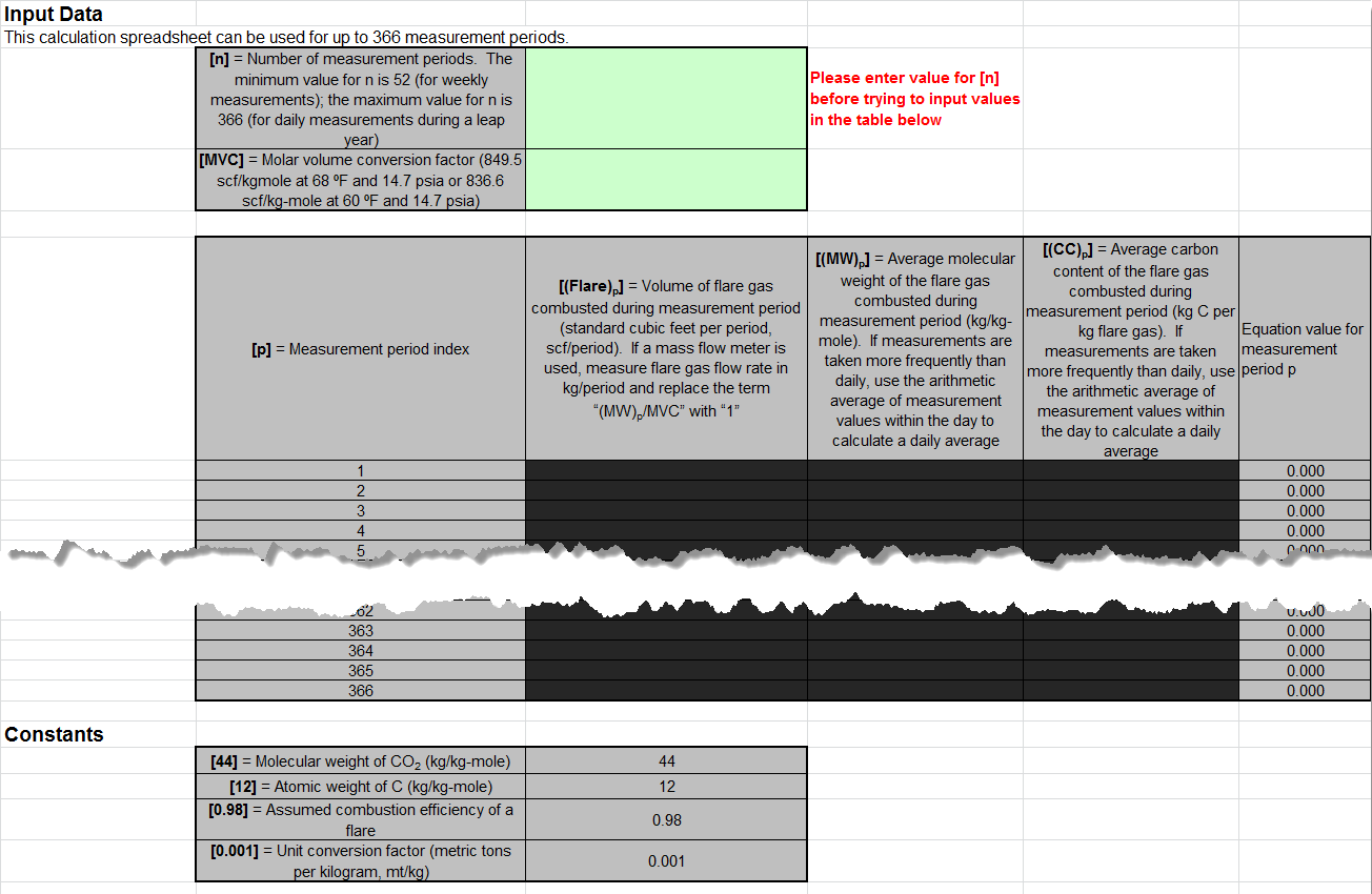
Begin by entering the facility name, your name, the unit name or identifier, reporting period, and any additional comments in the green input cells of the general information table located immediately below the equation in the calculation spreadsheet. This is for your records.
Next, enter the requested information in the green input cells in the first Input Data table. Based on your entries in the first Input Data table, a number of green input cells will be activated in the second Input data table. Enter the requested information in the green input cells in the second Input Data table.
The calculation spreadsheet will calculate the annual CO2 emissions for a fuel type combusted in a flare. The calculated value will be displayed in the red-bordered cell at the bottom of the spreadsheet. This value should be entered in e-GGRT and the Equation Y-4, Y-5 Calculation Spreadsheet for this flare. If different fuel types are separately monitored, add together the CO2 emissions calculated for each fuel type for a given flare and use the resulting sum for entry in e-GGRT and the Equation Y-4, Y-5 Calculation Spreadsheet for this flare.
Using the Equation Y-1b Calculation Spreadsheet
If you monitor gas composition and elect not to use Equation Y-1a, use the Equation Y-1b Calculation Spreadsheet to calculate annual CO2 emissions for one or more fuels combusted in a single flare using the mole percent concentration and carbon mole number of each compound in the flare gas stream. A separate spreadsheet should be used for each flare and fuel type combination. In nearly all cases, gas sent to a flare will be a mixture of different process gases, which are collectively considered to be fuel gas. As such, Equation Y-1b would be applied once for this fuel type. If you monitor separately the fuel gas sent to the flare and natural gas added to the flare for the purposes of preventing oxygen infiltration or ensuring adequate heating value of the gas flared, you should calculate the CO2 emissions separately for these fuels and sum the values for subsequent reporting. You do not need to separately calculate or report CO2 emissions from natural gas used as pilot gas for the flare. Equation Y-1b is provided below.
|
(Equation Y-1b) |
|
|---|
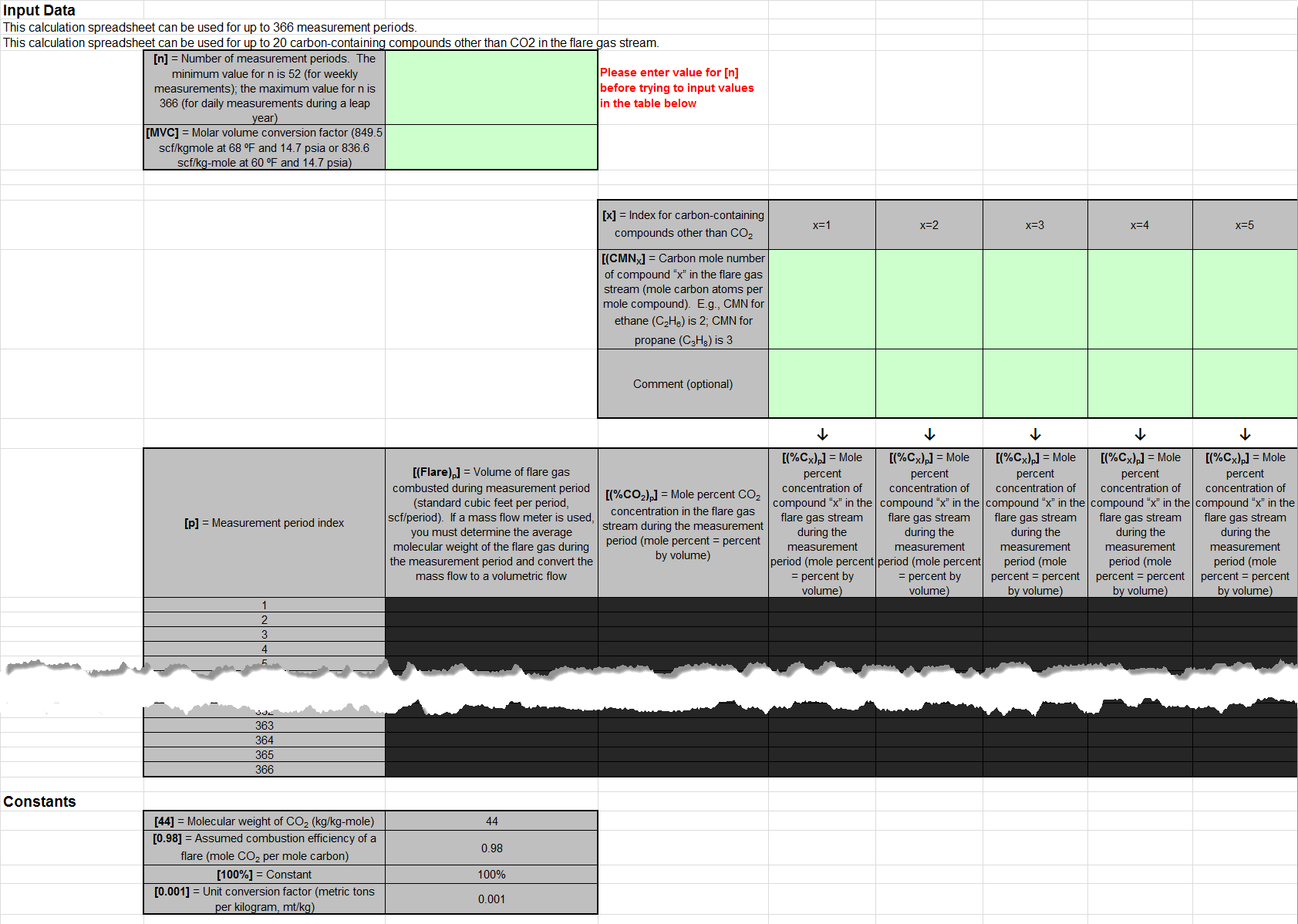
Begin by entering the facility name, your name, the unit name or identifier, reporting period, and any additional comments in the green input cells of the general information table located immediately below the equation in the calculation spreadsheet. This is for your records.
Next, enter the requested information in the green input cells in the first Input Data table. Based on your entries in the first Input Data table, a number of green input cells will be activated in the second Input data table. Enter the requested information in the green input cells in the second Input Data table. Space is provided for up to 20 carbon-containing compounds in the fuel stream.
Click image to expand
The calculation spreadsheet will calculate the annual CO2 emissions for a fuel stream combusted in a flare. The calculated value will be displayed in the red-bordered cell at the bottom of the spreadsheet. This value should be entered in e-GGRT and the Equation Y-4, Y-5 Calculation Spreadsheet for this flare. If different fuel types are separately monitored, add together the CO2 emissions calculated for each fuel type for a given flare and use the resulting sum for entry in e-GGRT and the Equation Y-4, Y-5 Calculation Spreadsheet for this flare.
Using the Equation Y-2 Calculation Spreadsheet
If you monitor heat content but do not monitor gas composition or if reporting under subpart Q per §98.172(b), you may use the Equation Y-2 Calculation Spreadsheet to calculate annual CO2 emissions for each fuel type combusted in each flare. A separate spreadsheet should be used for each flare and fuel type combination. In nearly all cases, gas sent to a flare will be a mixture of different process gases, which are collectively considered to be fuel gas. As such, Equation Y-2 would be applied once for this fuel type. If you monitor separately the fuel gas sent to the flare and natural gas added to the flare for the purposes of preventing oxygen infiltration or ensuring adequate heating value of the gas flared, you should calculate the CO2 emissions separately for these fuels and sum the values for subsequent reporting. You do not need to separately calculate or report CO2 emissions from natural gas used as pilot gas for the flare. Equation Y-2 is provided below.
|
(Equation Y-2) |
|
|---|
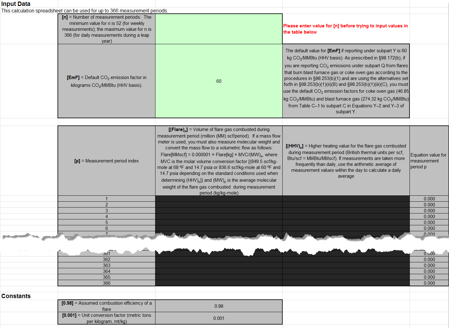
Begin by entering the facility name, your name, the unit name or identifier, reporting period, and any additional comments in the green input cells of the general information table located immediately below the equation in the calculation spreadsheet. This is for your records.
Next, enter the requested information in the green input cells in the first Input Data table. Based on your entries in the first Input Data table, a number of green input cells will be activated in the second Input data table. Enter the requested information in the green input cells in the second Input Data table.
If reporting under subpart Q per §98.172(b), you must report CO2 emissions from flares that burn blast furnace gas or coke oven gas according to the procedures in §98.253(b)(1) of subpart Y (Petroleum Refineries). When using the alternatives set forth in §98.253(b)(1)(ii)(B) and §98.253(b)(1)(iii)(C), you must use the default CO2 emission factors for coke oven gas (46.85 kg CO2/MMBtu) and blast furnace gas (274.32 kg CO2/MMBtu) from Table C-1 to subpart C in Equations Y-2 and Y-3 of subpart Y.
The calculation spreadsheet will calculate the annual CO2 emissions for a fuel type combusted in a flare. The calculated value will be displayed in the red-bordered cell at the bottom of the spreadsheet. This value should be entered in e-GGRT and the Equation Y-4, Y-5 Calculation Spreadsheet for this flare. If different fuel types are separately monitored, add together the CO2 emissions calculated for each fuel type for a given flare and use the resulting sum for entry in e-GGRT and the Equation Y-4, Y-5 Calculation Spreadsheet for this flare.
Using the Equation Y-3 Calculation Spreadsheet
If you do not measure the higher heating value or carbon content of the flare gas at least weekly or if reporting under subpart Q per §98.172(b), you may use the Equation Y-3 Calculation Spreadsheet to calculate annual CO2 emissions for each fuel type combusted in each flare using the average carbon content of the flare gas combusted. A separate spreadsheet should be used for each flare and fuel type combination. In nearly all cases, gas sent to a flare will be a mixture of different process gases, which are collectively considered to be fuel gas. As such, Equation Y-3 would be applied once for this fuel type. If you track separately the fuel gas sent to the flare and natural gas added to the flare for the purposes of preventing oxygen infiltration or ensuring adequate heating value of the gas flared, you should calculate the CO2 emissions separately for these fuels and sum the values for subsequent reporting. You do not need to separately calculate or report CO2 emissions from natural gas used as pilot gas for the flare. Equation Y-3 is provided below.
|
(Equation Y-3) |
|
|---|
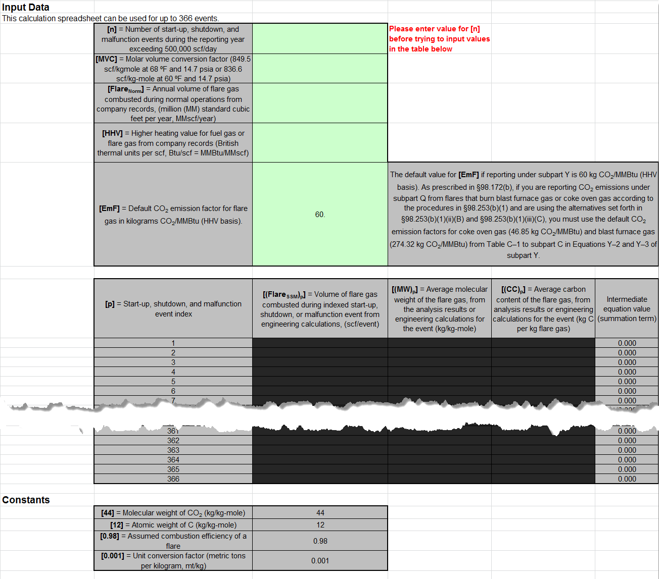
Begin by entering the facility name, your name, the unit name or identifier, reporting period, and any additional comments in the green input cells of the general information table located immediately below the equation in the calculation spreadsheet. This is for your records.
Next, enter the requested information in the green input cells in the first Input Data table. Based on your entries in the first Input Data table, a number of green input cells will be activated in the second Input data table. Enter the requested information in the green input cells in the second Input Data table.
If reporting under subpart Q per §98.172(b), you must report CO2 emissions from flares that burn blast furnace gas or coke oven gas according to the procedures in §98.253(b)(1) of subpart Y (Petroleum Refineries). When using the alternatives set forth in §98.253(b)(1)(ii)(B) and §98.253(b)(1)(iii)(C), you must use the default CO2 emission factors for coke oven gas (46.85 kg CO2/MMBtu) and blast furnace gas (274.32 kg CO2/MMBtu) from Table C-1 to subpart C in Equations Y-2 and Y-3 of subpart Y.
The calculation spreadsheet will calculate the annual CO2 emissions for a fuel type combusted in a flare. The calculated value will be displayed in the red-bordered cell at the bottom of the spreadsheet. This value should be entered in e-GGRT and the Equation Y-4, Y-5 Calculation Spreadsheet for this flare. If CO2 emissions are estimated for different fuel types, add together the CO2 emissions calculated for each fuel type for a given flare and use the resulting sum for entry in e-GGRT and the Equation Y-4, Y-5 Calculation Spreadsheet for this flare.
Using the Equation Y-4, Y-5 Calculation Spreadsheet
Use the Equation Y-4, Y-5 Calculation Spreadsheet to calculate annual CH4 and N2O emissions for each flare. A separate spreadsheet should be used for each flare. Equations Y-4 and Y-5 are provided below.
Per §98.172(b), if you are reporting under subpart Q, you must report CH4 and N2O emissions from flares according to the requirements in §98.33(c)(2) which employ Equation C-9a (not Y-4 and Y-5) and the emission factors for coke oven gas and blast furnace gas in Table C--2 to subpart C.
|
(Equation Y-4) |
|
|---|---|
|
(Equation Y-5) |
|
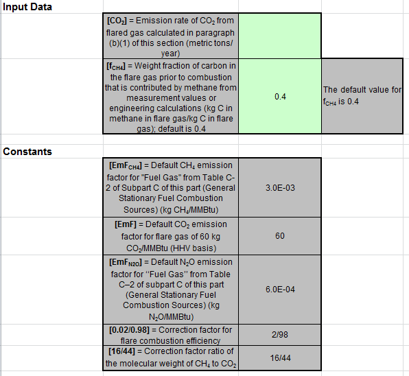
Begin by entering the facility name, your name, the unit name or identifier, unit description, and any additional comments in the green input cells of the general information table located immediately below the equation in the calculation spreadsheet. This is for your records.
Next, enter the requested information in the green input cells in the Input Data table.
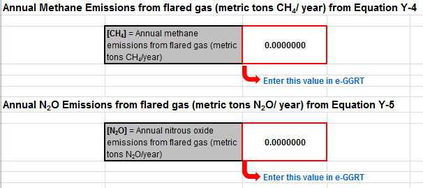
The calculation spreadsheet will calculate the annual CH4 and N2O emissions from this flare. The calculated values will be displayed in the red-bordered cells at the bottom of the spreadsheet. These values should be entered in e-GGRT for this flare.
Using the Equation Y-6, Y-7a, Y-7b Calculation Spreadsheet
For catalytic cracking units, fluid coking units, and catalytic reforming units that are required to use the methods provided in §98.253(c)(2)(i) through (iii), use the Equation Y-6, and potentially Y-7a or Y-7b Calculation Spreadsheet to calculate annual CO2 emissions from each catalytic cracking unit and fluid coking unit. A separate spreadsheet should be used for each unit. If you do not continuously monitor the volumetric flow rate of exhaust gas prior to the combustion of other fossil fuels, Equation Y-7a (based on percent concentrations of O2, CO2, and CO in gas stream inlet and/or exhaust gas stream) or Y-7b (based on percent concentration of N2 in gas stream inlet and exhaust gas stream) may be used to calculate the volumetric flow rate. Equations Y-6, Y-7a, and Y-7b are provided below.
|
(Equation Y-6) |
|
|---|---|
|
(Equation Y-7a) |
|
|
(Equation Y-7b) |
|
Begin by entering the facility name, your name, the unit name or identifier, reporting period, any additional comments, and the unit type in the green input cells of the general information table located immediately below the equation in the calculation spreadsheet. This is for your records.
Due to the extreme length of this spreadsheet, calculation results are displayed below the general information table near the top of the spreadsheet in addition to the bottom of the spreadsheet. Once the spreadsheet has been completely filled out, enter the results in the red-bordered cell in e-GGRT and in the Equation Y-9, Y-10 Calculation Spreadsheet.
Before transferring the data to e-GGRT and the Equation Y-9, Y-10 Calculation Spreadsheet, enter the requested information in the green input cells in the first Input Data table.
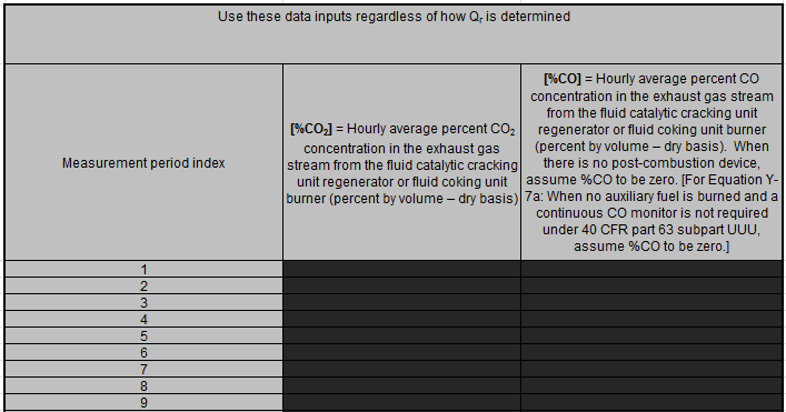
Based on your entries in the first Input Data table, a number of green input cells will be activated in the subsequent Input data tables. Enter the requested information in the green input cells in the second Input Data table shown below regardless of how Qr is determined.
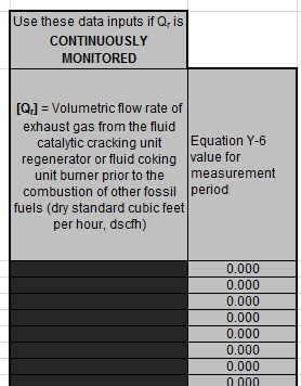
If you continuously monitor the volumetric flow rate of exhaust gas prior to the combustion of other fossil fuels, enter the requested information in the green input cells in the third Input Data table shown below.
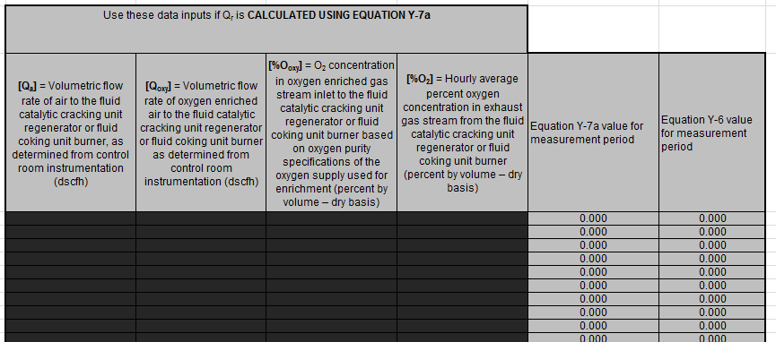
If you do not continuously monitor the volumetric flow rate of exhaust gas prior to the combustion of other fossil fuels and calculated Qr using Equation Y-7a (based on percent concentrations of O2, CO2, and CO in gas stream inlet and/or exhaust gas stream), enter the requested information in the green input cells in the forth Input Data table shown below.
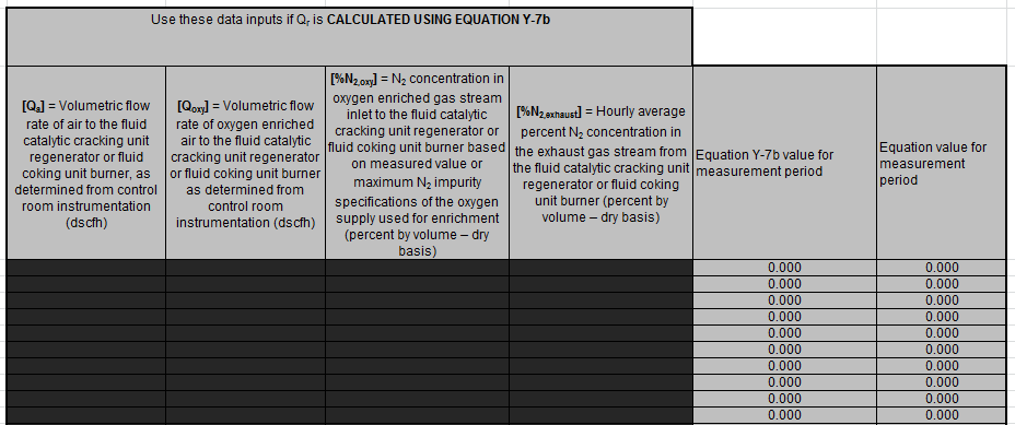
If you do not continuously monitor the volumetric flow rate of exhaust gas prior to the combustion of other fossil fuels and calculated Qr using Equation Y-7b (based on percent concentration of N2 in gas stream inlet and exhaust gas stream), enter the requested information in the green input cells in the fifth Input Data table shown below.
The calculation spreadsheet will calculate the annual CO2 emissions from each catalytic cracking unit and fluid coking unit. The calculated value will be displayed in the red-bordered cell at the bottom of the spreadsheet. This value should be entered in e-GGRT and the Equation Y-9, Y-10 Calculation Spreadsheet for this unit.
Using the Equation Y-8 Calculation Spreadsheet
For catalytic cracking units and fluid coking units with rated capacities of 10,000 barrels per stream day (bbls/sd) or less that do not monitor at least daily the O2, CO2, and (if necessary) CO concentrations in the exhaust stack prior to combustion of other fossil fuels, use the Equation Y-8 Calculation Spreadsheet to calculate annual CO2 emissions for each catalytic cracking unit and fluid coking unit. A separate spreadsheet should be used for each unit. Equation Y-8 is provided below.
|
(Equation Y-8) |
|
|---|
Begin by entering the facility name, your name, the unit name or identifier, reporting period, any additional comments, and the unit type in the green input cells of the general information table located immediately below the equation in the calculation spreadsheet. This is for your records.
Next, enter the requested information in the green input cells in the first Input Data table.
The calculation spreadsheet will calculate the annual CO2 emissions from each catalytic cracking unit and fluid coking unit. The calculated value will be displayed in the red-bordered cell at the bottom of the spreadsheet. This value should be entered in e-GGRT and the Equation Y-9, Y-10 Calculation Spreadsheet for this unit.
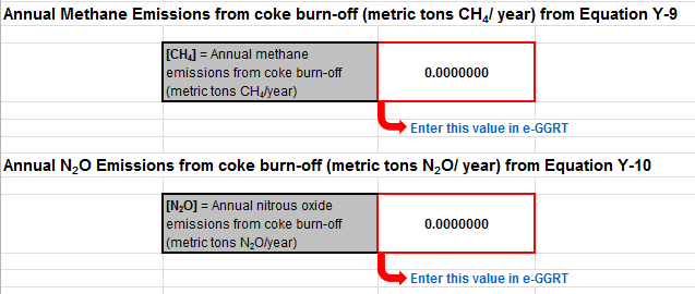
Using the Equation Y-9, Y-10 Calculation Spreadsheet
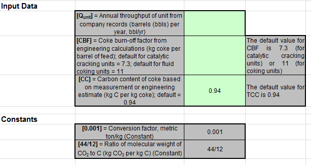
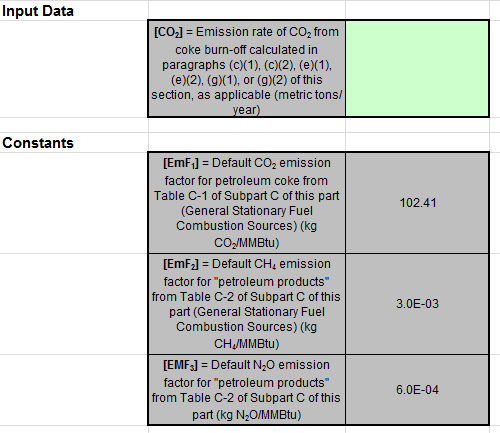
Use the Equation Y-9, Y-10 Calculation Spreadsheet to calculate annual CH4 and N2O emissions for each catalytic cracking unit, fluid coking unit, coke calcining unit, and/or catalytic reforming unit when the default emission factors are used (no calculation spreadsheets are provided if measurement data or site-specific emission factors are used). A separate spreadsheet should be used for each unit. The Equation Y-9, Y-10 Calculation Spreadsheet performs the calculations using Equations Y-9 and Y-10 provided below.
|
(Equation Y-9) |
|
|---|---|
|
(Equation Y-10) |
|
Begin by entering the facility name, your name, the unit name or identifier, unit description, any additional comments, and the unit type in the green input cells of the general information table located immediately below the equation in the calculation spreadsheet. This is for your records.
Next, enter the requested information in the green input cells in the Input Data table.
The calculation spreadsheet will calculate the annual CH4 and N2O emissions from this unit. The calculated values will be displayed in the red-bordered cells at the bottom of the spreadsheet. These values should be entered in e-GGRT for this unit.
Using the Equation Y-11 Calculation Spreadsheet
Use the Equation Y-11 Calculation Spreadsheet to calculate annual CO2 emissions for each catalytic reforming unit that does not monitor at least daily the O2, CO2, and (if necessary) CO concentrations in the exhaust stack prior to combustion of other fossil fuels. A separate spreadsheet should be used for each unit. Equation Y-11 is provided below.
|
(Equation Y-11) |
|
|---|
Begin by entering the facility name, your name, the unit name or identifier, reporting period, and any additional comments in the green input cells of the general information table located immediately below the equation in the calculation spreadsheet. This is for your records.
Next, enter the requested information in the green input cells in the first Input Data table. Based on your entries in the first Input Data table, a number of green input cells will be activated in the second Input data table. Enter the requested information in the green input cells in the second Input Data table.
The calculation spreadsheet will calculate the annual CO2 emissions from a catalytic reforming unit. The calculated value will be displayed in the red-bordered cell at the bottom of the spreadsheet. This value should be entered in e-GGRT and the Equation Y-9, Y-10 Calculation Spreadsheet for this unit.
Using the Equation Y-12 Calculation Spreadsheet
Except for non-Claus units electing to use the process vent method, use the Equation Y-12 Calculation Spreadsheet to calculate annual CO2 emissions from sour gas sent off site for sulfur recovery and annual CO2 process emissions from each on-site sulfur recovery plant. A separate spreadsheet should be used for sour gas sent off site for sulfur recovery and for each on-site sulfur recovery plant. The Equation Y-12 Calculation Spreadsheet performs the calculations using Equation Y-12 provided below.
|
(Equation Y-12) |
|
|---|
Begin by entering the facility name, your name, the unit name or identifier, unit description, any additional comments, and the unit type in the green input cells of the general information table located immediately below the equation in the calculation spreadsheet. This is for your records.
Next, enter the requested information in the green input cells in the Input Data table.
The calculation spreadsheet will calculate the annual CO2 emissions from sour gas sent off site for sulfur recovery or annual CO2 process emissions from each on-site sulfur recovery plant. The calculated value will be displayed in the red-bordered cell at the bottom of the spreadsheet. This value should be entered in e-GGRT.
Using the Equation Y-13 Calculation Spreadsheet
Use the Equation Y-13 Calculation Spreadsheet to calculate annual CO2 emissions for each coke calcining unit. Use a separate spreadsheet for each unit. Equation Y-13 is provided below.
|
(Equation Y-13) |
|
|---|
Begin by entering the facility name, your name, the unit name or identifier, reporting period, and any additional comments in the green input cells of the general information table located immediately below the equation in the calculation spreadsheet. This is for your records.
Next, enter the requested information in the green input cells in the Input Data table.
The calculation spreadsheet will calculate the annual CO2 emissions from a coke calcining unit. The calculated value will be displayed in the red-bordered cell at the bottom of the spreadsheet. This value should be entered in e-GGRT and the Equation Y-9, Y-10 Calculation Spreadsheet for this unit.
Using the Equation Y-14, Y-15 Calculation Spreadsheet
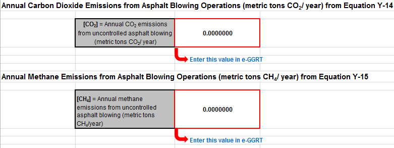
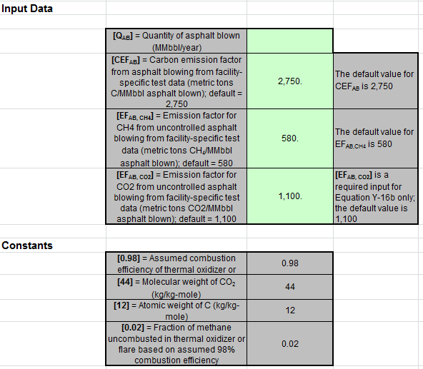
For uncontrolled asphalt blowing operations and asphalt blowing operations controlled by vapor scrubbing, use the Equation Y-14, Y-15 Calculation Spreadsheet to calculate annual CO2 and CH4 emissions for asphalt blowing operation. Equations Y-14 and Y-15 is provided below.
|
(Equation Y-14) |
|
|---|---|
|
(Equation Y-15) |
|
Begin by entering the facility name, your name, the unit name or identifier, reporting period, and any additional comments in the green input cells of the general information table located immediately below the equation in the calculation spreadsheet. This is for your records.
Next, enter the requested information in the green input cells in the Input Data table.
The calculation spreadsheet will calculate the annual CO2 and CH4 emissions from asphalt blowing operations. The calculated values will be displayed in red-bordered cells at the bottom of the spreadsheet. These values should be entered in e-GGRT.
Using the Equation Y-16a, Y-16b, Y-17 Calculation Spreadsheet
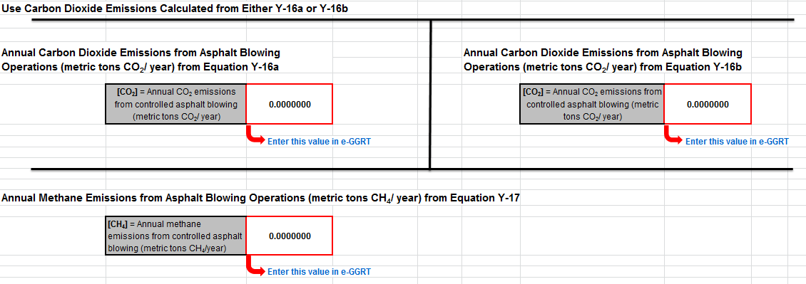
For asphalt blowing operations controlled by thermal oxidizer or flare, use the Equation Y-16a, Y-16b, Y-17 Calculation Spreadsheet to calculate annual CO2 and CH4 emissions for asphalt blowing operation. Equations Y-16a, Y-16b, and Y-17 are provided below.
|
(Equation Y-16a) |
|
|---|---|
|
(Equation Y-16b) |
|
|
(Equation Y-17) |
|
Begin by entering the facility name, your name, the unit name or identifier, reporting period, and any additional comments in the green input cells of the general information table located immediately below the equation in the calculation spreadsheet. This is for your records.
Next, enter the requested information in the green input cells in the first Input Data table.
The calculation spreadsheet will calculate the annual CO2 and CH4 emissions from asphalt blowing operations. The calculated values will be displayed in red-bordered cells at the bottom of the spreadsheet. If you used an emission factor for CO2 from uncontrolled asphalt blowing from facility-specific test data enter the result from Equation Y-16b into e-GGRT, otherwise enter the result from Equation Y-16a into e-GGRT. The result for CH4 should also be entered in e-GGRT.
Using the Equation Y-18 Calculation Spreadsheet
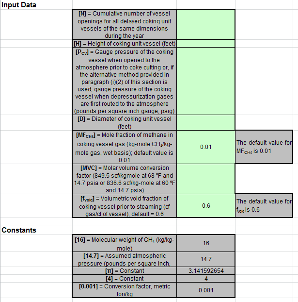
Use the Equation Y-18 Calculation Spreadsheet to calculate annual CH4 emissions for each set of similar delayed coking vessels. A separate spreadsheet should be used for each set of different delayed coking vessels. Equation Y-18 is provided below.
|
(Equation Y-18) |
|
|---|
Begin by entering the facility name, your name, the unit name or identifier, reporting period, and any additional comments in the green input cells of the general information table located immediately below the equation in the calculation spreadsheet. This is for your records.
Next, enter the requested information in the green input cells in the Input Data table.
The calculation spreadsheet will calculate the annual CH4 emissions from a set of similar delayed coking vessels. The calculated value will be displayed in the red-bordered cell at the bottom of the spreadsheet. If you elect to use the process vent method for the depressurization cycle, calculate CH4 emissions during depressurization using the Equation Y-19 Calculation Spreadsheet and add that value to the CH4 emissions calculated using the Equation Y-18 Calculation Spreadsheet for vessel openings. If you have multiple sets of delayed coking vessels, add together the CH4 emissions from all delayed coking vessels and enter the sum total into e-GGRT for delayed coking units.
Using the Equation Y-19 Calculation Spreadsheet
Use the Equation Y-19 Calculation Spreadsheet to calculate annual CO2, CH4, and N2O emissions for each process vent not covered in paragraphs (a) through (i) of §98.253 or for other sources electing to use this method. A separate spreadsheet should be used for each process vent. Equation Y-19 is provided below.
|
(Equation Y-19) |
|
|---|
Begin by entering the facility name, your name, the unit name or identifier, reporting period, any additional comments, and the unit types in the green input cells of the general information table located immediately below the equation in the calculation spreadsheet. This is for your records.
Next, enter the requested information in the green input cells in the first Input Data table. Based on your entries in the first Input Data table, a number of green input cells will be activated in the second Input data table. Enter the requested information in the green input cells in the second Input Data table.
Click image to expand
The calculation spreadsheet will calculate the annual CO2, CH4, and N2O emissions from for a process vent. The calculated values will be displayed in the red-bordered cells at the bottom of the spreadsheet. These values should be entered in e-GGRT for this process vent (or for this process unit for units electing to use the process vent method).
Using the Equation Y-20 Calculation Spreadsheet
Use the Equation Y-20 Calculation Spreadsheet to calculate annual CH4 emissions for blowdown systems unless the process vent method is selected. Equation Y-20 is provided below.
|
(Equation Y-20) |
|
|---|
Begin by entering the facility name, your name, the unit name or identifier, reporting period, and any additional comments in the green input cells of the general information table located immediately below the equation in the calculation spreadsheet. This is for your records.
Next, enter the requested information in the green input cells in the Input Data table.
The calculation spreadsheet will calculate the annual CH4 emissions from blowdown systems. The calculated value will be displayed in the red-bordered cell at the bottom of the spreadsheet. This value should be entered in e-GGRT for this unit.
Using the Equation Y-21 Calculation Spreadsheet
Use the Equation Y-21 Calculation Spreadsheet to calculate annual CH4 emissions for equipment leaks unless the alternative method is selected. Equation Y-21 is provided below.
|
(Equation Y-21) |
|
|---|
Begin by entering the facility name, your name, the unit name or identifier, reporting period, and any additional comments in the green input cells of the general information table located immediately below the equation in the calculation spreadsheet. This is for your records.
Next, enter the requested information in the green input cells in the Input Data table.
The calculation spreadsheet will calculate the annual CH4 emissions from equipment leaks. The calculated value will be displayed in the red-bordered cell at the bottom of the spreadsheet. This value should be entered in e-GGRT for this unit.
Using the Equation Y-22 Calculation Spreadsheet
Use the Equation Y-22 Calculation Spreadsheet to calculate annual CH4 emissions for storage tanks other than those processing unstabilized crude oil unless the alternative method is selected. Equation Y-22 is provided below.
|
(Equation Y-22) |
|
|---|
Begin by entering the facility name, your name, the unit name or identifier, reporting period, and any additional comments in the green input cells of the general information table located immediately below the equation in the calculation spreadsheet. This is for your records.
Next, enter the requested information in the green input cells in the Input Data table.
The calculation spreadsheet will calculate the annual CH4 emissions from storage tanks other than those processing unstabilized crude oil. The calculated value will be displayed in the red-bordered cell at the bottom of the spreadsheet. This value should be entered in e-GGRT for this unit.
Using the Equation Y-23 Calculation Spreadsheet
Use the Equation Y-23 Calculation Spreadsheet to calculate annual CH4 emissions for storage tanks that process unstabilized crude oil. Equation Y-23 is provided below.
|
(Equation Y-23) |
|
|---|
Begin by entering the facility name, your name, the unit name or identifier, reporting period, and any additional comments in the green input cells of the general information table located immediately below the equation in the calculation spreadsheet. This is for your records.
Next, enter the requested information in the green input cells in the Input Data table.
The calculation spreadsheet will calculate the annual CH4 emissions from storage tanks that process unstabilized crude oil. The calculated value will be displayed in the red-bordered cell at the bottom of the spreadsheet. This value should be entered in e-GGRT for this unit.


